Lab 03. Build Your Own Bot
For this lab, we will walk you through building the first version of your robot. You will add to this basic design for the rest of the term, slowly improving it until the eventual robot tournament, where you will compete against all other teams for the best times through an obstacle course.
We suggest using a modular approach to building the robot. Rather than trying to make the whole system work together all at once, build the smallest possible part of the system you can, test it thoroughly, and then proceed to the next stage. Plan to test, plan for failure, plan to repeatedly rebuild and test again, and you will succeed.
For today, you will just build the robot's chassis and drive system. You may decide to build multiple versions of your robot, so if your team would like to build two in parallel, feel free to do that. You will likely have to rebuild your robot from scratch more than once, so do not plan to make this the final design. Instead, spend your creative time testing this initial driving module thoroughly.
Pre-lab
- Review Pulse Width Modulation from lecture.
- Review the Motor Driver from lecture.
- Review the idea of a Bill of Materials
Lab
You may choose to do multiple parts of this lab in parallel, or work on everything together at the same time as a team. In the end, everyone will be responsible for knowing how every part of the robot works.
0. Group work
Review the group work policy document. Make a copy, fill out template, and submit to Canvas. You will probably want to keep a live version of the document somewhere that everybody can access.
The point of this exercise is to set out clear expecations, not to create rules to punish each other and yourself with. Make this a living document, i.e., update it as you need.
You will also need to create and maintain a GitHub repo for your code and/or a shared drive for your robot documentation. You can use other platforms as needed, but the robot code needs to be in a well-maintained GitHib repo that includes usage instructions. Use this repo as a template: github.com/COGS-300/MyRobot.
1. Chassis
The chassis of the robot is the load-baring framework. In our case, we start with a plastic mounting plate to which we attach all of our components.
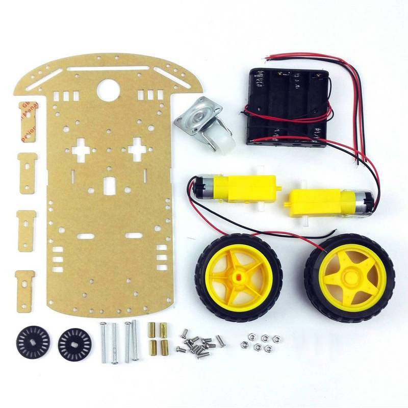
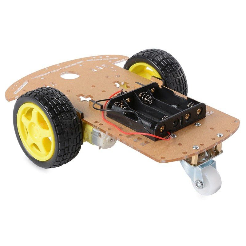
Here is the bill of materials (BOM) for the chassis. There are a few things to notice. First, it does not include every single design detail, nor does it include accurate colours. It's not the greatest drawing, in fact, it's made just by tracing the image above by hand. It took less than 10 minutes to make. It shows some assembly but it's not Ikea catalogue level of detail. This is a "good enough" BOM drawing for something that is in-progress. It includes a part list and counts below.
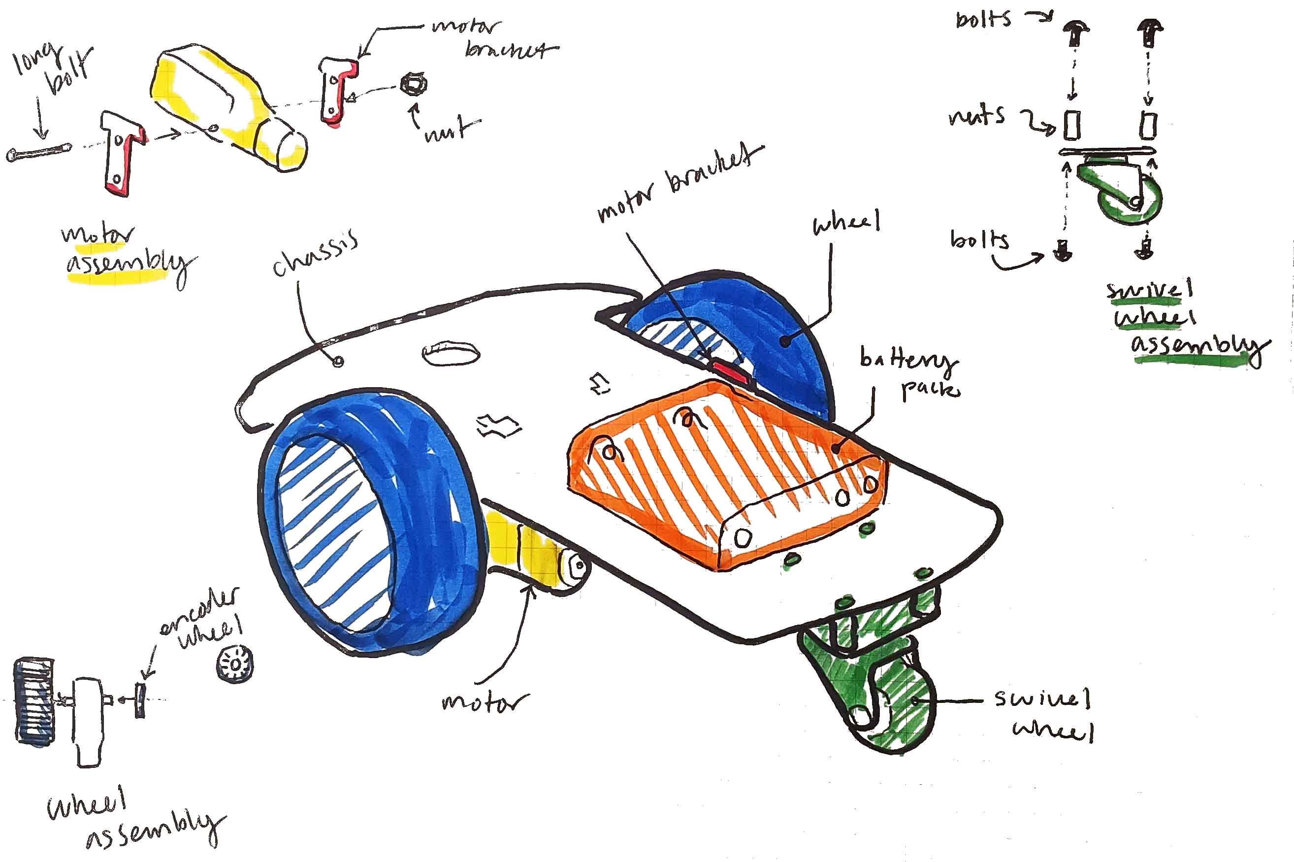
| Part | count |
|---|---|
| Wheel | 2 |
| Motor | 2 |
| Motor bracket | 4 |
| Encoder wheel | 2 |
| Swivel wheel | 1 |
| Small bolts | 10 |
| Large bolts | 4 |
| Small nuts | 6 |
| Large nuts | 4 |
Draw your own BOM for the robot and maintain along with your group's documentation. Your TAs will ask for it when you come with debugging questions.
You can watch the following video for a similar build. The black encoder wheels are good to think about applying to the robot, but are not going to be used this week.
Note that the build below does not include an Arduino, so do not permanently attach your breadboard to your chassis yet.
2. Prototyping the control circuit
In parallel to the above, start to prototype the driving circuit. You will need an Arduino, motor driver, one or two motors, and a power source.
The purpose of building this circuit in parallel (or as a separate module) is to decompose your design workflow and debugging process. When you inevitably run into issues with your whole system, testing each module independently will assist in making a whole-system diagnosis.
Here is a video that describes the wiring process:
Conceptually, there are a few notes to make. Your Arduino is the control module at the top of the control hierarchy. It is running the code that will command the motors to move. It uses 5V logic, which is powerful enough to transmit signals, but probably not powerful enough to drive motors (due to friction, etc.). The motor driver is the target module at the bottom of the control hierarchy. It uses 5V logic and 12V power to drive the motor.
You need to power your motor driver with an external 12V power source. You can experiment with lower or higher voltages, up to a maximum of 24V, although you really shouldn't need to go that high and run the risk of burning your components out. The Arduino is basically controlling transistors with a lower voltage that act as a gateway for a higher voltage to flow.
This is what is meant by a transistor being a type of amplifier: you're taking a lower voltage signal from the Arduino and using it to control a higher voltage.
3. Driving forwards and backwards
Each side of the motor driver uses three pins: one to enable driving, and two for direction. The motor outputs Out1 and Out2 are driven by enA, in1; in2. Out3 and Out4 are driven by in3, in4, and enB.
The pins here might be different than the video or other documentation. Either change the physical pin configuration, or the code below to match. ~ indicates a PWM-capable pin.
int enA = 9;   // Enable pin for Motor A — must be a PWM-capable pin
int in1 = 8;   // Direction control pin 1 for Motor A
int in2 = 7;   // Direction control pin 2 for Motor A

void setup() {
    // Set motor control pins as outputs
    pinMode(enA, OUTPUT);
    pinMode(in1, OUTPUT);
    pinMode(in2, OUTPUT);
}

void loop() {
    digitalWrite(in1, LOW);  // direction
    digitalWrite(in2, HIGH); // direction
    digitalWrite(enA, HIGH); // enable
}
The code above will drive a motor at maximum speed in some direction. Whether it's forward or backwards depends on many things: whether you switched a pin around, the orientation of your motor, etc. You get to define forwards and backwards by testing your circuit.
The template repo demonstrates how you can package the above code into a single function. The most helpful code design will be to create functions called forward, backward, and stop that you can call from your loop.
5. Speed Control
Using the principle of pulse-width modulation (PWM), we can vary the amount of time that the enable pin is on to control the speed of the motor.
Briefly, PWM works by rapidly outputting a HIGH signal, then a LOW signal over and over again in a cycle. When outputting to a device like a motor, the proportion of high-to-low signal will determine the amount of speed. The more time the signal is HIGH, the more time motor spends ON. This is the duty cycle, i.e., the cycle of performing useful work.
In Arduino, we control the PWM pins using analogWrite(pin, amountOn). Due to the way bit logic works, the number ranges from 0-255.
void loop() {
    digitalWrite(in1, LOW);  // direction
    digitalWrite(in2, HIGH); // direction
    analogWrite(enA, 255);   // max speed
}
Create or amend the functions in Motor.ino to take a speed and drive the motor forwards and backwards a different speeds.
6. Driving the robot
If you haven't yet, it's now time to integrate the test circuit and the chassis build. You want to be able to consistently do the following high-level actions (among others):
- Drive the robot forwards
- Drive the robot backwards
- Turn the robot left while driving
- Turn the robot right while driving
- Turn the robot in place (one wheel forward, the other backward)
You may need to calibrate the robot depending on many things like power supply voltage, weight, friction, attachments, etc. Due to the difference between static and rolling friction, you may notice that a minimum speed is lower while driving than while stopped. All of this is expected behaviour, but it may seem unexpected the first time you make the robot move.
Encapsulate your driving commands into well-tested, callable functions.
7. Robust Testing (homework)
Demonstrate your working prototype by making a video and posting it to Piazza by the night before your next lab. You will also demonstrate the prototype during lab to your TA. Update your BOM to include all the parts that you added. Use it as the basis of your debugging materials. Upload it along with your video.
Submit your group work agreement on Canvas and post to GitHub.
We ask that you do "something" above and beyond for this lab. The minimum requirement for next lab is that you create a robust testing framework to demonstrate your robot's abilities.
Here are some ideas for going above and beyond:
- Create an interface in Serial Monitor that accepts testing commands
- Create a Processing.org sketch that accepts testing commands
- Use other circuitry such as a potentiometer and LEDs to display debugging information
- Your own creative idea
As usual, you will be marked on the following scale:
- 5: Exceptional demonstration of lab concepts (exceeds requirements)
- 4: Good demonstration of lab concepts (meets requirements)
- 3: Reasonable demonstration of lab concepts (one or two requirements unclear)
- 2: Missing one or two lab concepts
- 1: Missing most lab concepts
- 0: No attendance/no completion.